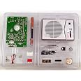
📻 Build it. Own it. Hear the difference.
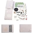
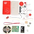
The TECSUN 2P3 AM Radio Receiver Kit is a premium DIY project designed for enthusiasts seeking superior AM reception and hands-on learning. With higher sensitivity than most AM radios, a portable battery-powered setup, and a complete radio case, it combines educational value with stylish portability.
Item Weight | 1 Pounds |
Item Dimensions L x W x H | 11"L x 8"W x 3"H |
Style | Fun Radio Kit |
Color | Multicolor |
Hardware Interface | 3.5mm Audio |
Frequency | 108 MHz |
Speaker Maximum Output Power | 120 Watts |
Power Source | Battery Powered |
Tuner Type | AM |
E**N
Fantastic Kit!
I technically should knock of one star because, as other reviewers have mentioned, the kit IS missing two 10K-ohm resistors; and also because the documentation shows an empty IF transformer shield can soldered to the circuit board (covering the detector diode and a couple of other small parts) and that shield can is missing. I'm sure the radio will work fine without the shield can, but you MUST replace the two missing resistors or it won't work. BUT . . . the rest of the kit in it's implementation, documentation, and design is so outstanding that I'm still giving it 5 stars. It's just that good, and we haven't seen anything this good in America since Heath-Kit lamentably went out of business.Other reviewer stated that he had to cut holes in the plastic case in order to get a good fit, that is just plain false. Folks, this is a kit, you have to expect to do some work here! It's not going to just snap together like some Lego blocks. Doing the work, taking your time and doing it right with some finesse, and winding up with a nice thing you can have some pride of accomplishment in, that's all part of the kit building experience. I found that if you position the volume control and headphone jack on the PCB and hold it there with a little piece of blue painter's masking tape (do one of them first, then the other) in their positions and DON'T solder yet, then place the PCB in the case and test for fit with the holes in the case . . . if the fit is not good, reposition the part and secure again with the tape. Once the fit is perfect, carefully remove the PCB without disturbing the position of the part being held by the tape, and then with the tape holding the part in it's perfect location, you solder it down to the PCB. That's what I mean by taking your time and doing the job with some finesse.Again to the reviewer who complained he had to file the little volume control daughter board after breaking it off the main PCB, it's to be expected, it's a kit, not a pile of Lego blocks. Another totally invalid complaint IMHO.The 4-color poster is fantastic, there are NO errors on it. The reviewer who complained about the electrolytic capacitor markings was just nit-picking, Thee negative side of the capacitors is marked plainly on both the pictorial chart AND on the PCB itself. I have been working as a professional in Avionics for over 38 years, and most ALL capacitors of that type I've seen have the NEGATIVE side marked. In the kit, the parts themselves, the pictorial, and the PCB all are plainly marked as to which side is the negative side, so no problem there at all IMHO.I have an extensive "junk box" full of electronic parts at home, so I had no problem replacing the two missing resistors. Still, no excuse for that, they need to fix that issue so that people don't have to go to Radio Shack and get something that is supposed to be included in the kit. I also had plenty of "junk" miniature IF transformers, so I gutted one of them and installed the can on the PCB over the detector components as shown by the outline on the PCB and in the documentation. Missing parts issue solved.I turned on the radio and it worked right away. Then I aligned it via the simple method in the documentation and it was working just fine, with the stations 560 and 1450 showing up on the station dial in their proper relative positions. Maybe the reviewer who complained about the stations not being in the right place was in too big of a hurry to read the documentation about the part that says it NEEDS to be aligned. Again, it's a kit radio, NOT a snap-together pile of Lego blocks.I then did what I consider to be a "proper" alignment using a voltmeter to monitor the AVC voltage at the points marked "TP1 and TP2" in the documentation, and using an RF signal generator set to 455khz to align the IF, and then set to 540KHz and 1650Khz to alternately align the inductor and trimmer capacitors to get the stations to appear almost perfectly with the tuning dial markings. I then had a remarkably sensitive and selective little receiver; that tells me they used good parts for the tuned circuits in the radio considering there are just a couple of transistors in there doing all the "work".It even received my talk radio station inside a metal aircraft hangar, better than any radio anyone else has in the shop (but still it wasn't as loud as it can get outside the building). I then noticed it I place my hand, or a small metal plate near the back of the radio inside the metal hangar, it picked up as good as it could outside. So an idea came to mind - I took the back of the radio off again, and I covered the whole inside surface of it with "1000 mile per hour tape" AKA aircraft battle damage tape, it's metal (aluminum) tape and you can get a roll of it at any of the big box home improvement stores, usually in the section that has the duct work for heating and air conditioning (or sometimes it's in the paint department with the masking tape). I carefully cut around all of the ventilation holes in the radio's back (even though it doesn't get hot and doesn't need ventilation) mostly because the sound from the speaker can get out through those slots and makes the radio's sound fuller. VOILA, not the radio pick up just as good in metal or rebar reinforced concrete structures as it does outside in open air.Then I went on a camping trip way out in the desert 155 miles as the crow flies from my home town's low-power talk radio station. The little radio picked up that station with plenty of volume and no static - unlike all 4 of the car radios of the folks who were at camp with me, none of the car radios (two stock ones and two after-market ones) could even pick it up. So I'm very impressed with the engineering, sensitivity and selectivity of this little radio.Overall, despite the missing parts, it was a pleasure to build and a pleasure to listen to. Oh, and the batteries last a long time I'm sure, because I've been listening to it almost everyday for 5-7 hours each day at work, plus on Saturdays in the house (talk radio junky here) for almost 2 months now, and there is no sign of the radio's volume being any lower than the first time I used it.A well deserved 5-Stars, and that's not even taking into account it's educational value to kids who are just learning radio electronics. But I sure wish Tecsun would hurry and get the missing parts issue solved for those kids big and small that don't have a huge collection of electronic parts laying about the house as I do.
J**S
Great little radio with a couple little issues.
This radio is a kit so, if course, you must put it together. This means soldering all the components to the board, which requires some soldering skills. The directions are adequate but could certainly be better. They do Not give you a blow by blow step quide for each component as you would see in a Heathkit or Elenco. However, if you have even basic common sense and a bit of electronics knowledge, you really shouldn't have that much trouble building it. There are a couple quarks with it though. One is there are 3 test points that have a cut in a trace so after it's assembled, you are to test current at these points. If they are in range, in theory, you should be able to bridge the gap to close it. I found it was necessary to add a tiny bit of a discarded lead to bridge these points. One of them is in a pretty tight spot. The other thing is that the volume control works backwards. By this I mean when you first turn it on, what would normally be the lowest volume is the highest! That's pretty annoying. It was easily fixed, but it required a modification. I desoldered the 2 points for either side of the volume pot, and swapped the leads. It now works as expected.The circuit is a unique design in that with only 3 transistors, it's able to achieve quite a sensitive and selective radio! All of the actual receiver section is done with those 3 transistors! Yet it does have 2 IF stages. The audio amp is done with a single IC. The volume is quite good, and everything matches up well. The alignment is quite simple. It helps to have another radio to compare with so you know what station you are actually listening to. The finished radio is quite small and very usable. If course not many people are into a radio that is only AM now a days but I found it to be a fun experience and I do still listen to AM. Part of the reason it's as selective as it is, is due to the fact it uses a ceramic filter between the 2 IF stages. It has quite a large farrite bar antenna for such a small radio. Don't let the minor issues deter you from building this kit. I had a lot of fun doing it and got a good radio to boot so it was well worth the cost. I just wish they had designed it so the volume worked as normal. That is the reason I gave it 4 instead of 5 stars.
Trustpilot
1 week ago
5 days ago