Description
⚡ Command Your Tech Universe with 4-Channel Power!
- MULTI DEVICE MASTERY - 4-channel relay board lets you orchestrate multiple devices simultaneously
- POWER UP YOUR PROJECTS - Handles up to 10A AC/DC loads for heavy-duty appliance control
- SMART AUTOMATION READY - Perfect for smart home setups, industrial PLCs, and advanced DIY builds
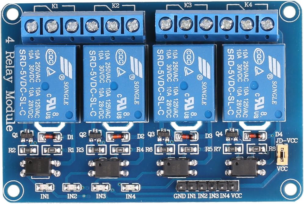
- VISUAL CONTROL FEEDBACK - Built-in LEDs keep you instantly informed of relay status
- PLUG PLAY COMPATIBILITY - Seamlessly integrates with Arduino, Raspberry Pi, and all major MCUs
The JBtek 4 Channel DC 5V Relay Module is a robust, PCB-mountable interface board designed for seamless control of high-current devices up to 10A at 250V AC or 30V DC. Compatible with all major microcontrollers including Arduino and Raspberry Pi, it features four independent relays with LED indicators for real-time status monitoring, making it an essential component for smart home automation, industrial control, and advanced DIY electronics projects.